Goals

While the original skateboard had some interesting electronic features, I had bigger plans for this version. I wanted to support on-the-fly adjustment of parameters, as well as getting data out of the skateboard while it was being ridden. On the old board I had one multi-colored LED that was my only way of communicating with the outside world. I also wanted to make upgrading the software as easy as possible so that I had no excuse to try new code.

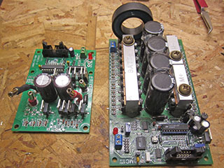
Similar to the mechanical components, there were several ideas I wanted to cary over from the original skateboard. The gyroscop/accelerometer and microcontroller had worked out well. I had used a cheap reed switch as a deadman's switch with no issues. Using a large contactor to control master power was another keeper. I had been happy with the OSMC based motor controller. All these items made it over into this skateboard.

Design

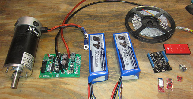
Looking around on the SparkFun site, there were all kinds of fun toys to try to incorporate. I settled on the following new components:

  • An Infared receiver would allow me to send commands to the skateboard via remote control.
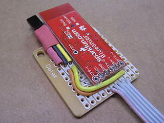
  • A Bluetooth module would allow me to output arbitrary debug information from the skateboard, as well as send commands to it.
  • An addressable RGB LED strip would work well to give visual feedback to the rider. Plus it would look cool.
  • I added a few headlights just for fun. Since the board is bi-directional, I'd have two on each end.
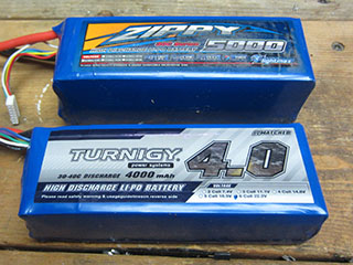
  • There are significant 5 volt power requirements, so I added a 10 amp DC to DC converter to take the 22.2 volts from the 6 cell LiPoly battery down to 5 volts.

Additionally, I wanted to make some improvements on old functions and add a few features as well.

  • I wanted to make sure that the deadman's switch would always kill power to the motor. On the previous version, the deadman's switch was completely under software control, so if the main program crashed, the kill switch would not have any effect. This was potentially dangerous. I wanted to make sure the kill switch really killed the motor.
  • Voltage detection. Skate One had no concept of how much juice was left in the battery. I wanted to make sure this version could shut itself down if necessary
  • Related, I needed a software controllable power switch so that I could turn off the skateboard completely via software.

Here's a diagram of the various power buses, and which components attach to them.

5Vz/c6o4EP9r/LEdIGjrj7Xt3Xszr3ed8+7d3Y8RojIPiYOxtu+vfxvICiS2BTVFqTMqWUKy7O5nd/MFeuR28fx7SpfzBx6yuOc54XOP3PU8z3VdH/4k5SWnDPuDnDBLo1BVKgjj6CdTREdR11HIVpWKgvNYRMsqMeBJwgJRoU15XO1iSWfYfEEYBzQ2qf9GoZjn1GtPsSzpX1g0m2M37mCYn1mJF2wjZFO6jsVFRoJz8vSCYlvqrp6dvEjU9S+q7KnykiYVjn5yvqgQUrYqRKXuNqrefUKfKn1OeBqytEKKo+RHWYzkHlSZcg4NyaPF8y2LpTpRU0OfTAPHDfru1fB66l3kzfxWs/ZWuilLFKuHNaik+0TjtRJFzxvQxbJHRslkJf8871LW+A5fOBVDr6NJCkczeWSojiXhTZryDZSCmK5WUQC15mIRA8GFQxpHM6mXmE1FfjELDYN6/eYKEQNaGF8wkb5IW8hrXziXg6FH8mY2hfX1la7mJcNDWspiKqKnKgtUaXS27WLb6yOPgLltl66j2lHYvFJFbGHF12nA1EVlvWjtkMHb7Qiazph4ox2syKfTFavUgYOSsApSZhn1rESJtGQlf44foBVN+Zt5JNh4SQNZ3oAzq+peNcJSwVB6h2pcF5uviiXlu4jUsvbxsl2KrsitgZCUl65A6RB0kBF7jsR/6pQ8/h+Oncv+vrgBVjJrfEPHpqA/Bkb+sKpHLDaFUR8NoBmMjgARX91zSf3Sc4Lb1GwAjF/qtqT1LBDRSVYBgtioZAgBaFQGnJFETQRR9kadWERhKC8YxXTC4hENfsxSvk7CWx7zPECRafbZ4k5Fd9VPEcAa4jGz8rc8MIFPRQdofAd72p2tWvV7CmrHhHQCzEhMSxyrYgbr/UGd2/TuKlnW1RaoXQ3U+8ZGvR0XQW4f1SprLRnAd0icZQrsOXfRE+TVMhV6Lyn6+LjoEk1kiPY2AuNVDRSB3Y9VccVmC7jt+4IEMGkjq/wYlHjXdjJIF/l7ByUgWCrvFqstZYVVfX6xn6Z8FcaUc3AsyF4b1nYn25A/OlBveZKh7jQxbAiuTQxj9C2J9Q8mwnWU8BMQla/ZpIejslZEZY6WzsPfod3p4RaFW9MfNsj6USV6T019n6F/DH9H9n06w9iPLV+GM38lU+p3bkSR48U0xwPjKuZuOF7AGUirAwa3zojhjLBPEEjWsU/QZR+K/e0tWMY+9tOUL2u+whyr1Ehrzt13ZHjriO8wx0nf7uHXGYs0Wp5kimrE3R2pwsflXWbm/4XREEx0nuP6xIS1ze9bEZZaJetKoNpGIOuBauuqDg5UOKayHahUP035shWotq7+UwWqDG/dCFTIZld8h49AtJ/kHmuA69dc2DrUd2A/Tfmy5jt27lfouO8obSw5f99hTo498o2cgXWyZPcMkly/zU0GXp1dBufke7Fs3ff6ujr29b19SwsrOsPYT1O+rPneXXNbnfe9r+x3OEvfa84Q3aSnuoTTb3O1yzOnYh64AEtrX076DqdWg5E54/IXY6EU0SYSwfwkw/kAU+dTWCvEzcolCX5NpincHEjx9ETV5vQerkSURDWCo79hqzUY2snJqtXZPWKO0L8+/HOCUmo1l8Z9iueaS/f1iTuiMrSj59IDbfMlcVRPTXNpAyVDraEj5dIGw6qfpnzZyqXJrmFc13PpHG/dyKURal3xHTB6/CDfYezN2dt34GYL275D9dOUL2u+4zMu9Od464jvqLMh+jhPCpUfOKg8bmDrKSLEzlsPJeTDxrb2Ww/09Vx9GXZff+TqOaq9xxKIOfAml6RzOwNzoLwawxz5YGoZvSqpOtQn7G7Vrks48+0Yejphb0nViM77LqkaQ1FLS6o6w+8tqb7Gl610Akfgnyud6NB2DN9cEx9RAQIHRnU9foseebyDPhjX0PlqTpfyMHiBlx5k70EYvTODpOt7woWAtzBYWD3Q5ycM74PBuex9dNdRY1IJisXLHXLlFS/tIPe/AA==

All this added up to a much more ambitious electronics set up than I'd attempted before. I filled many pages in a notebook with circuit diagrams, googled around a bit on various topics, and then jumped into building a prototype.

Implementation

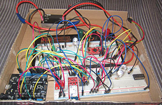
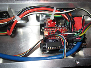
I got the trusty breadboard out and started attacking pieces of the overall system. I made sure I could use a transistor to keep the contactor engaged. I used a voltage divider to get voltage readings from the 6 cell LiPoly battery. I used transistors to switch the high-current LED headlights on and off. I verified I could read infrared signals, and read/write Bluetooth data.

The addressable LED strip was a bit of a challenge. I was using a Netduino2 as the microcontroller. This microcontroller runs interpreted bytecode, which resulted in it being too slow to send the very timing sensitive signals to the LED strip. I eventually decided to use an Arduino microcontroller to deal with the LED strip, and to leave the rest of the tasks to the Netduino2.

After prototyping each part of the overal design, I designed a custom shield for the Netduino microcontroller. Instead of making one by hand, I decided to use 123d.Circuits to layout the board, and to have them manufacture the PCB for me. I laid out the board on the website, and clicked "Order". A few weeks later 3 boards showed up, costing me a total of $30. You can access the design here.
I soldered all the components onto the custom board. I definitely placed a few components too close together, and made a few non-critical mistakes, but overall things worked out well. I gave the board a few quick tests, and all looked good. This is a giant step up from the previous skateboard shield.
The original skateboard used 5 amp hour batteries. I switched to 4 amp hour batteries this time around. This was mostly to make them fit in the 2" tall frame, and partially because I'd never used anywhere near the full capacity of the original batteries. Note that these batteries can output 30 to 40C, equating to 120 to 160 amps continous. I'm using two in parallel, giving me access to a max of 240 to 320 amps. Battery technology has really come a long way.
I also switched from the MC1 motor controller to a basic OSMC motor controller. They both use the same control mechanism, so in theory it was an easy swap. The OSMC is much smaller, cheaper, and still available from Robot Power. However, I ran into serious problems getting the board to behave. This turned out to not be an issue with the board, but the cable and routing I was using. I'll write about that in the future, as I learned a lot of about the OSMC that may be helpful to others.
I was careful this time around to orientate the microcontroller so that I could plug a USB cable into it without having to tear everything apart. Note that both the Netduino and Arduino ports have plenty of clearance.
I found some panel-mount USB cables, and mounted them to the underside of the skateboard. Now I don't have to take anything apart in order to upload new code, and have a separate port for the Arduino and the Netduino.
I had to mount the IR and Bluetooth module outside the normal frame so that signals could be recieved and transmitted. This required a small board, and an enclosure that bolted to the frame.
I may have "optimized" my space usage a bit too much. Everything fits, but just barely. I hadn't planned on the exteranl IR/Bluetooth module, which made the cable routing a bit challenging. I got everything to fit eventually.

While I was working on the electronics, I also spent time designing and building the software. Read about that process here.